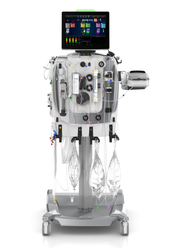
What is the communication unit?
The communication unit consists of the touch screen display and the machine alarm status light. It is used to input and receive all system information.
- THE STATUS LIGHTS
- THE SCANNER
- THE USER INTERFACE

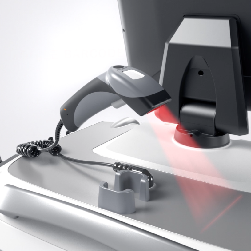
The scanner
The scanner is located at the top of the machine.
It is used to scan the disposable sets during set-up mode and can scan the patient ID. It pre-populates parameters and capabilities via barcode/QR code.
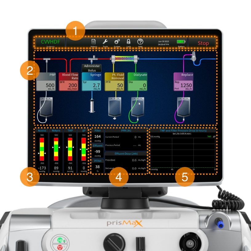
The User Interface
Touch screen display with intuitive graphics and icons providing step-by-step instructions for operating the PrisMax machine.
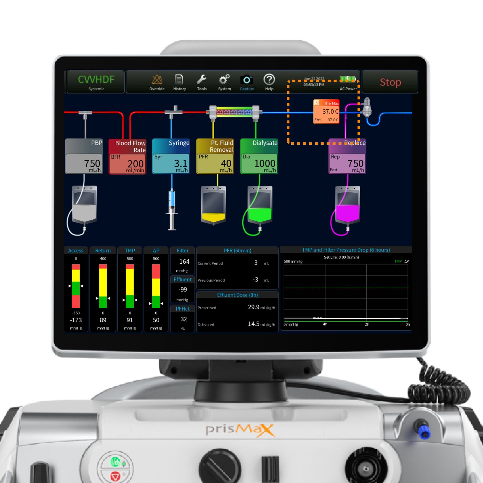
The touch screen is built up around 5 sections:
- TOOLBAR
Includes various buttons to access therapy data and prescription information - FLOW RATES
Shows each flow rate with the ability to change the flow rates - PRESSURE BARS
Indicates current operating pressure measurement, operating range, and alarm limits - EFFLUENT AND PFR DOSING PARAMETERS
Shows the prescription value and what has been delivered - PRESSURE HISTORY & SET LIFE
Displays the filter drop pressure and the TMP/TMPa (as applicable) pressure over the last 6 hours of treatment and current set life (hr:min)
Continue the walkthrough explaining the Blood Flow Management on the PrisMax System.
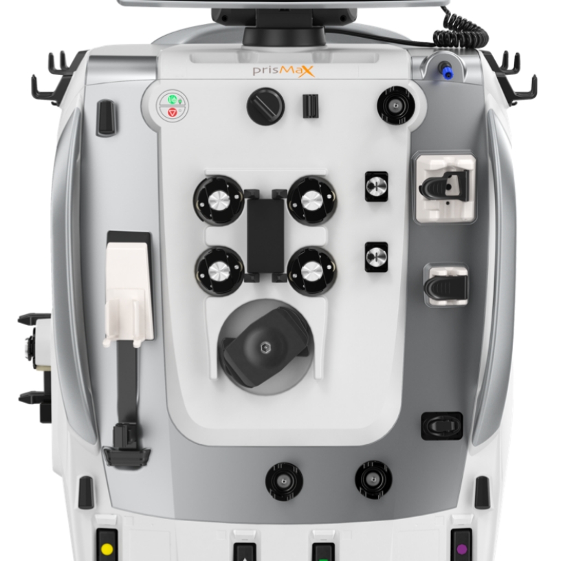
What is Blood Flow Management?
The PrisMax system’s Blood Flow Management section consists of pumps, pressure sensors, and a deaeration chamber, all located in the middle section of the machine.
- ATTACH CARTRIDGE & LOAD SETS
- BLOOD PUMP
- SOLUTION PUMPS
- SAFETY SYSTEM
- PINCH VALVES
- PRESSURE SENSORS
- SYRINGE PUMP
- BLOOD WARMER
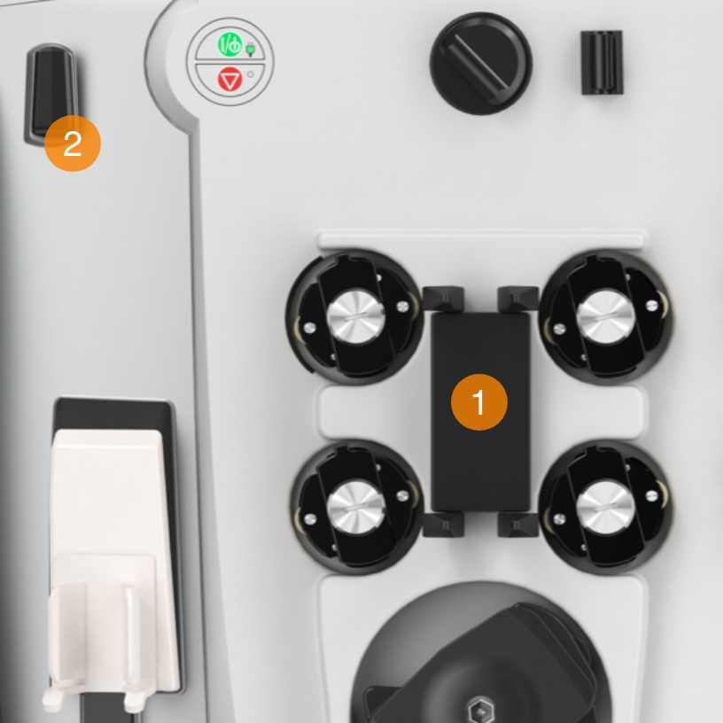
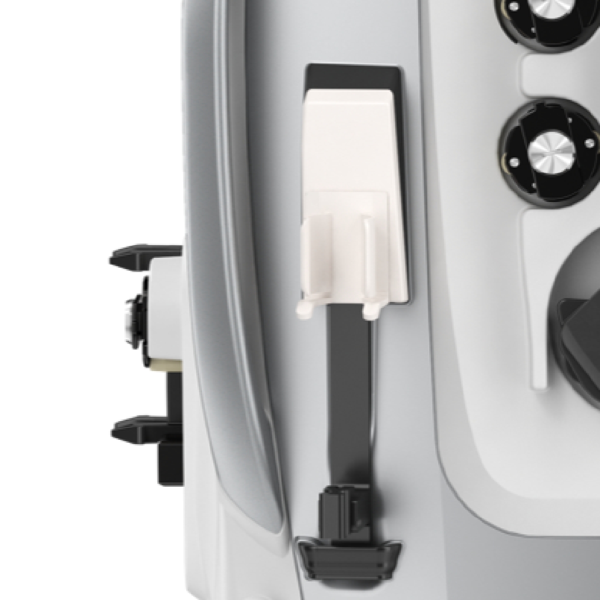
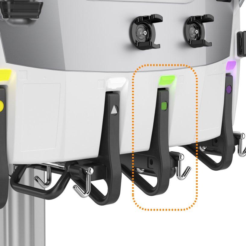
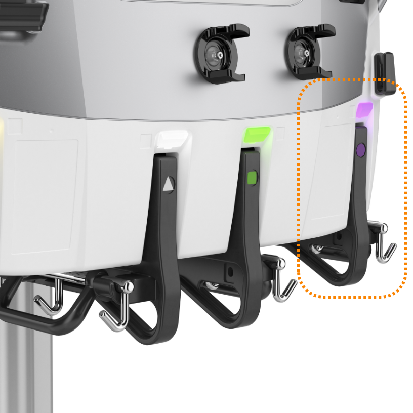
Attach cartridge & load sets
- CARTRIDGE HOLDER
Holds the cartridge in the disposable set. Fits with all sets - LINE HOLDER
Designed to hold /control lines from the disposable sets
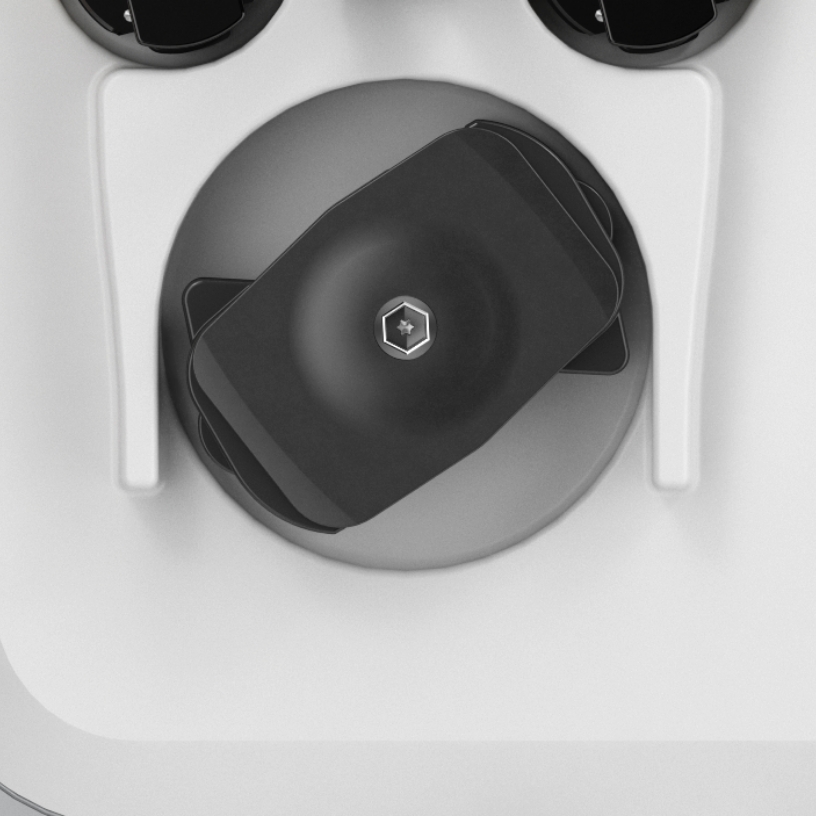
Blood pump
Pumps blood through the blood flow path of the disposable set.
Runs in mL/minute.
Capable of running 0-450 mL/min. based on therapy setting and disposable set in use.
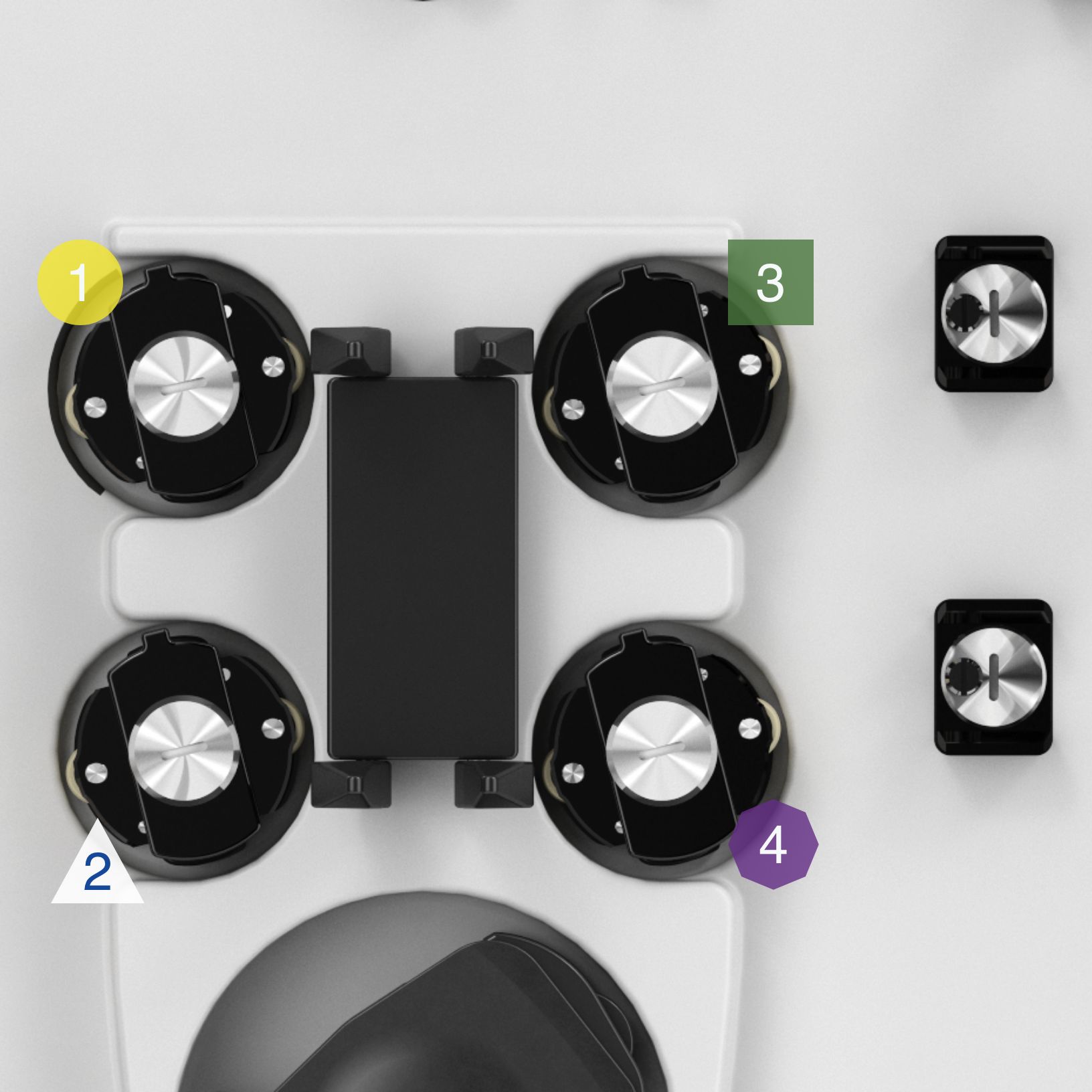
Solution pumps
Controls solution flow rates from the scales - directs solutions into the filter and the bloodstream.
Runs in mL/hour.
- EFFLUENT PUMP
Pumps ultrafiltrate/dialysate. It controls the removal of solution from the filter as well as patient ultrafiltrate
Color-coded YELLOW to coordinate with the disposable set/Scales - PRE-BLOOD PUMP (PBP)
The solution from the corresponding scale will go in before the BLOOD PUMP and the FILTER. (Pumps solution into the blood access line at a location after patient blood enters the line and before the blood pump)
Color-coded WHITE to coordinate with the disposable set/Scales - DIALYSATE PUMP / REPLACEMENT PUMP 2
Running CVVHD + CVVHDF:
Pumps dialysate solution into the fluid compartment of the filter
Running CVVH: serves as REPLACEMENT 2 (Solution into blood flow)
Color-coded GREEN to coordinate with the disposable set/Scales - REPLACEMENT PUMP
Infuses replacement solution into the flow path. Depending on the prescribed therapy, the pump infuses solution into the flow path pre-filter, post-filter, or both. This is set by a pinch valve
Safety system
- DEAERATION CHAMBER HOLDER
Some actions during treatment can add a small amount of air into the set and change the fluid level in the deaeration chamber. The machine uses the Liquid Level Sensor (LLS) in the chamber holder to check the fluid and adjust or warn appropriately. - AIR BUBBLE DETECTOR (ABD)
Detects bubbles and micro-bubbles. If detected it may generate a red alarm (a safety feature) - Air in Blood - and engage the RETURN LINE CLAMP (see point #3).
Serves as a safety control for the Deaeration Chamber function - RETURN LINE CLAMP
The return line clamp closes to prevent blood or air from passing to the patient. The clamp automatically closes when power is off, during some self-tests, or in case of a possible patient safety hazard. Installing tubing under the clamp engages a tubing detection switch. - BLOOD LEAK DETECTOR (BLD)
Houses the effluent line - a sensor makes it possible to check for/detect blood in the effluent line. Problems with the therapy or the filter may result in blood in the effluent line - DISCHARGER RING
Holds the effluent line of the disposables - designed to remove static electricity generated in the PrisMax system and ground it to prevent possible interference with other (ICU) equipment
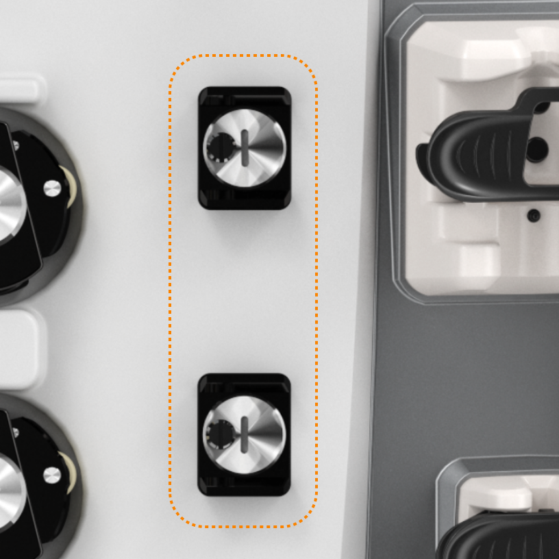
Pinch Valves (Upper & Lower)
Controls solution flows based on interaction and end-user choice of therapy and replacement modalities.
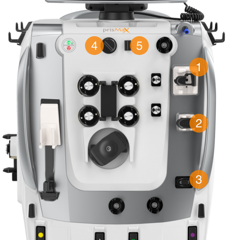
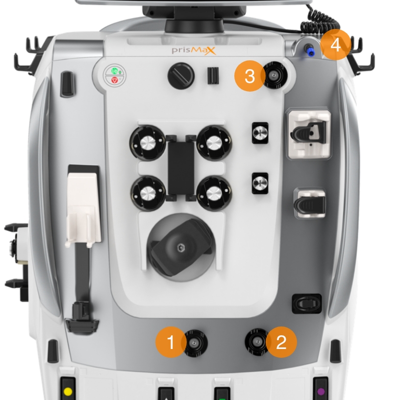
Pressure sensors
Monitors pressure within the system when blood and fluids are moved through the system.
- ACCESS PRESSURE SENSOR
Monitors the access line pressure, how much pressure it takes to pull blood through the vascular access device, from the patient, and into the filter - FILTER PRESSURE SENSOR
Monitors the pressure of the blood entering the filter. It works with the Return
Pressure Port (#4), which monitors filter return pressure.
Together, they calculate the filter pressure drop and how the filter is running - EFFLUENT PRESSURE SENSOR
Monitors the effluent line pressure and the amount of pressure needed to get the effluent flow across the membrane from inside the filter to the effluent bag.
Helps calculate transmembrane pressure - RETURN PRESSURE PORT
Connects to the deaeration chamber pressure monitor line on the disposable set. A fluid barrier at the distal end of the monitor line protects the return pressure sensor from accidental blood entry. Enables non-invasive monitoring of return line pressure
Syringe pump/holder
It can hold either 20 mL. or 50 mL. syringe (depending on configuration).
Solution-filled syringe used for:
- Heparin: in Systemic Anticoagulation mode
- Calcium (Ca): using Citrate-Calcium software*
*Software not approved for use in the US.
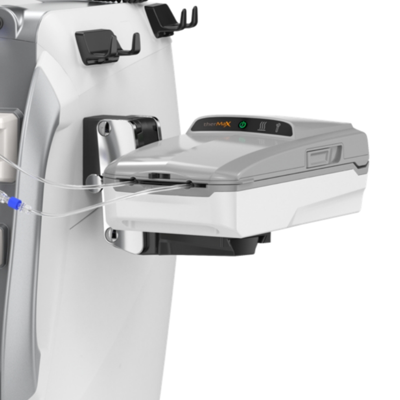
The TherMax blood warmer
An intelligent, high-efficiency blood-warming device with low extracorporeal blood volume. Once the prescription temperature is entered, the operator does not need to make further management or power adjustments to maintain it.
Warms the blood to the set temperature. Blood temperature between 35,0 C and 38,0 C.
Lights and Icons on top for operation status, communicating directly with the PrisMax machine.
Connected to the PrisMax system by VGA cable on the Back Panel (middle socket).
The TherMax disposable bag is designed to allow maximum heat transfer from the warmer. It has inlet and outlet connectors to connect in line with the blood filter set.
Continue the walkthrough explaining the Fluid Management on the PrisMax System.
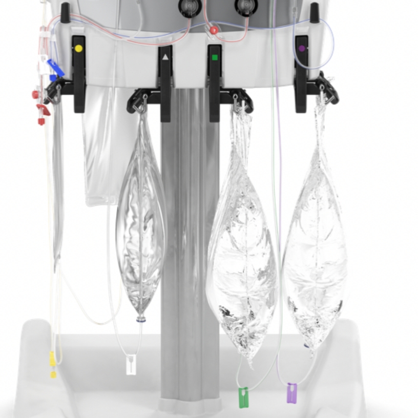
What is Fluid Management System?
Scales hold solution bags to be used. Scale software monitors the weight of each fluid bag to precisely control solution flow rates and patient fluid removal (PFR).
- EFFLUENT SCALE
- PRE-BLOOD PUMP
- DIALYSATE SCALE
- REPLACEMENT SCALE
- AUTO-EFFLUENT (AE) ACCESSORY
- DRIP TRAY
Color coding, icons, and geometrical shapes correspond to specific pumps and disposable sets. Corresponding light for each scale to indicate status.
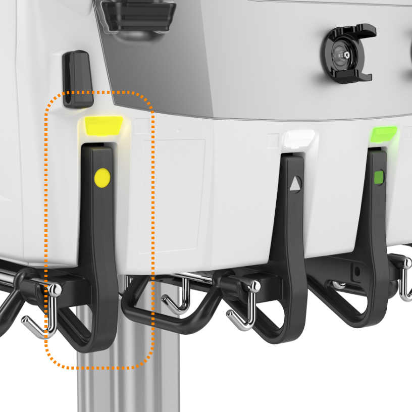
Effluent scale
Color-coded: YELLOW circle
The effluent scale monitors the volume of fluid removed from the patient during treatment. This scale ensures that the effluent pump maintains the required flow rate, calculated by the plasma loss rate and replacement fluid rate.
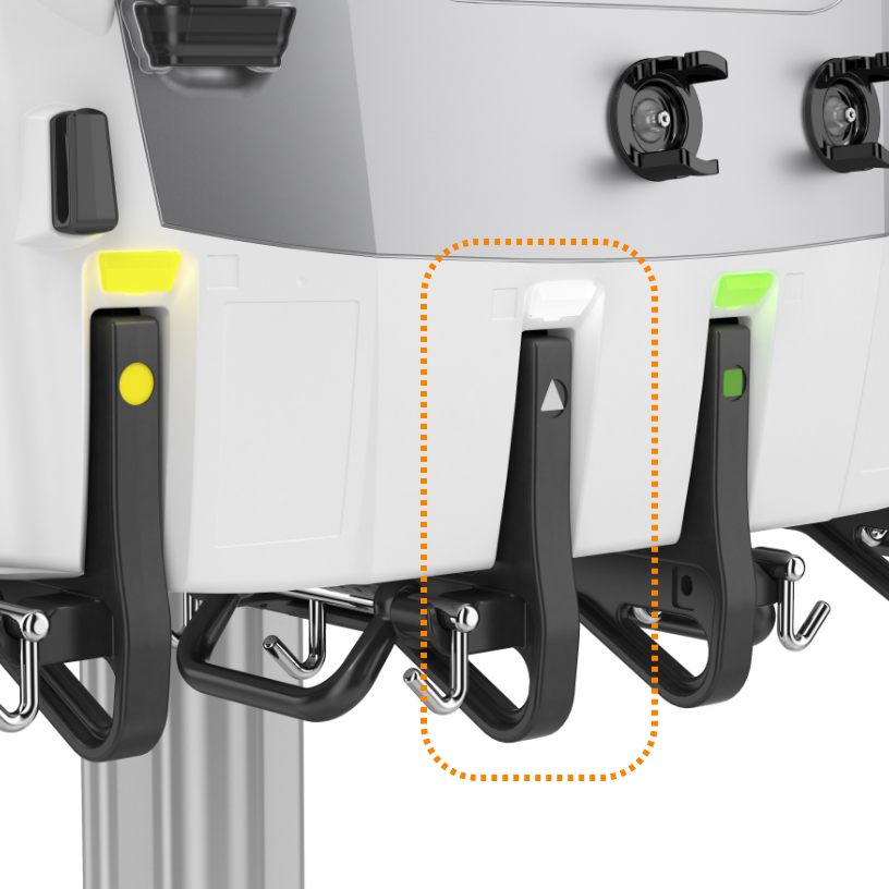
Pre-blood pump scale (PBP)
Color-coded: WHITE triangle
The PBP scale monitors the volume of fluids infused before the blood enters the filter. This scale plays a critical role in therapies that require pre-filter fluid infusion, such as anticoagulants in regional citrate anticoagulation. The PBP scale ensures that the appropriate amount of fluid is infused, preventing clotting and maintaining system functionality.
Dialysate scale
Color-coded: GREEN square
This scale is responsible for tracking the dialysate solution's weight, ensuring the correct amount of fluid is used during dialysis. While not utilized in TPE, the dialysis scale plays a crucial role in Continuous Renal Replacement Therapy (CRRT) by managing the balance between the removal of waste products and fluid administration.
Replacement scale
Color-coded: PURPLE octagon
The replacement scale is essential for managing the weight and volume of replacement fluids administered to the patient. This scale adjusts for various container sizes, allowing for precise fluid management down to as little as 10 mL increments. The system ensures that fluid replacement is balanced against effluent removal to maintain patient stability.
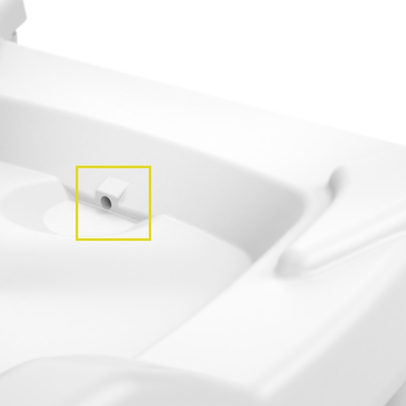
Drip Tray
Integrated in the base of PrisMax is a well and a sensor to help detect leaking fluids from the solution bags or fluid circuits.
An alarm goes off if leaked fluid accumulates past a fixed limit.
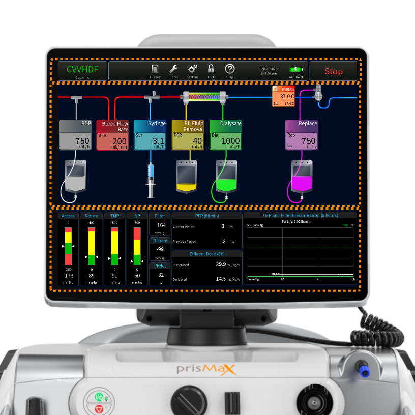
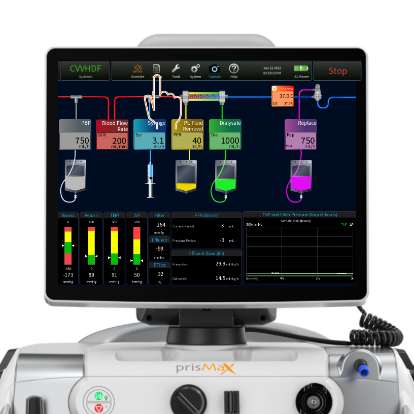
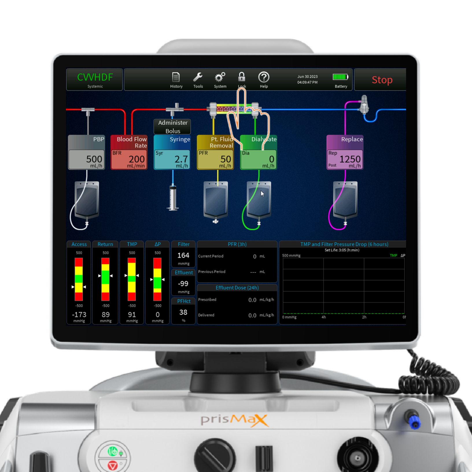
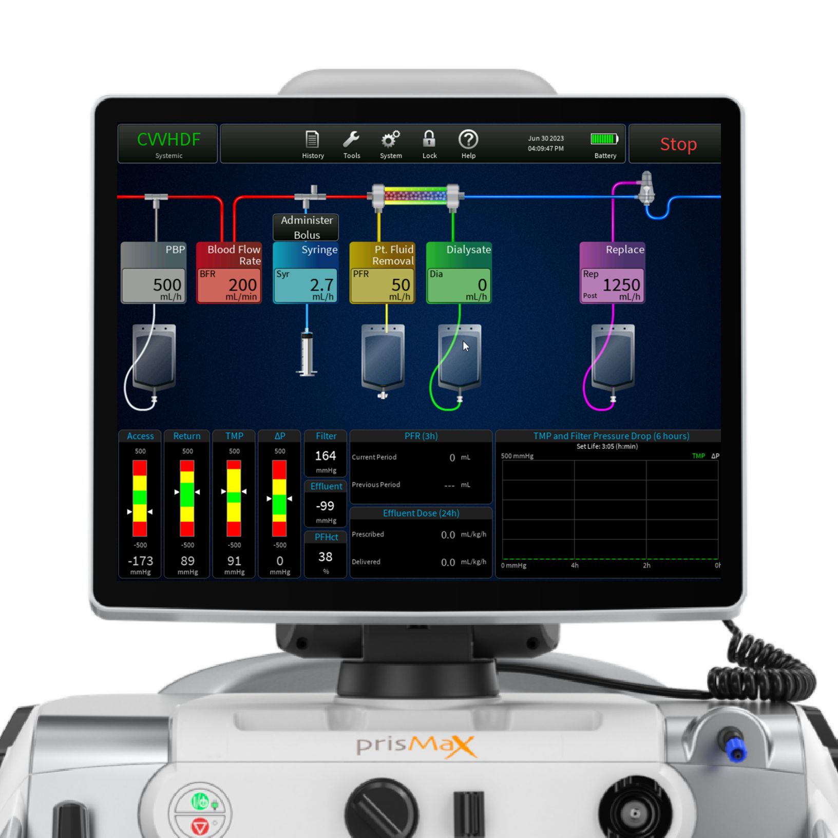
The operations screen
The operations screen is the home screen during therapy.
Tap or press the touch-screen to access and operate tools and functions.
- TOOLBAR
- MAIN SCREEN - FLOW RATES / FILTER & BAG SETUP (INCLUDING THERMAX)
- OPERATION PARAMETERS
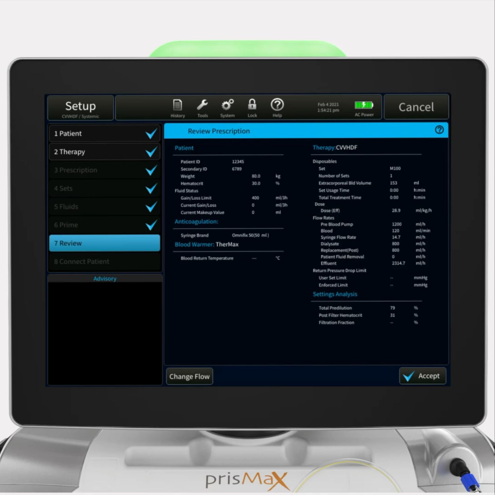
Toolbar - Therapy mode
- Shows selected treatment modality and anti-coagulant mode
- Tap to bring up current prescription for review
- Tap PATIENT to change patient weight and hematocrit
- Button modes: SETUP, THERAPY TYPE & END
Toolbar - Alarm
The toolbar can include the following options - but not all buttons appear in all situations.
Override – to turn off. Depending on the type of alarm/type of severity.
|
This is shown if an active alarm is minimized/docked.
|
 |
|
This is shown if an alarm is overridden or turned off.
|
 |

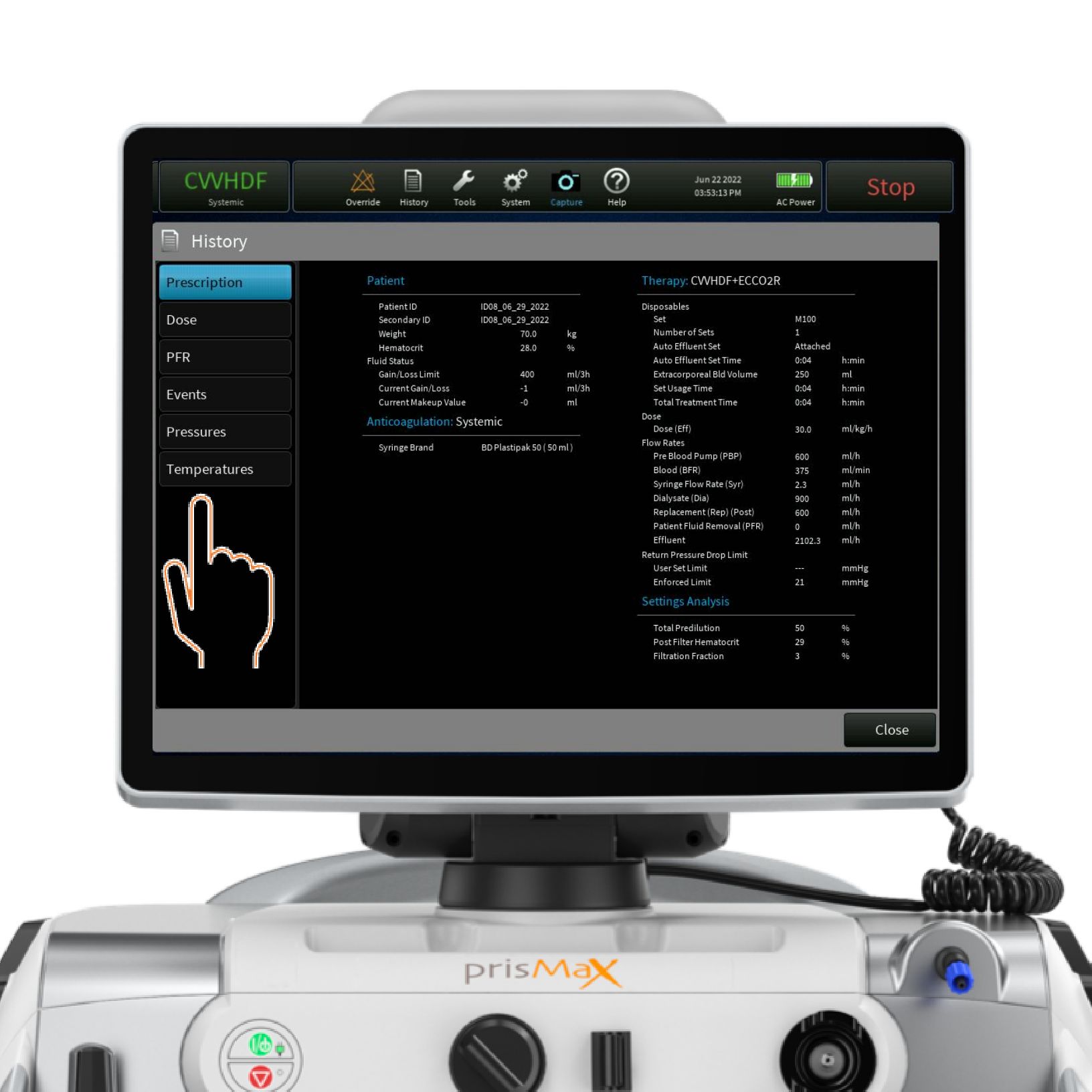
Toolbar - History
Tap HISTORY to access the HISTORY screen. Active during THERAPY or END mode.
Toolbar - History
Tap/Press to access:
- Prescription – to view prescription history
- Dose – to view dose delivery; percentage delivered and in DAILY, LAST 24 Hrs. and TOTAL intervals
- PFR – Patient Fluid Removal overview in intervals: 1 Hr., 8 Hrs., 24 Hrs. and TOTAL
- Events – Event log; overview of all auto-logged events since onset; time-stamped. Events can be sorted by event types
- Pressures – Pressure graph; view pressure levels over time (trends). Select one or more pumps to populate the graph
- Temperatures – Temperature graphs: view temperature levels over time; select one or more TherMax temperature sensors to populate graph
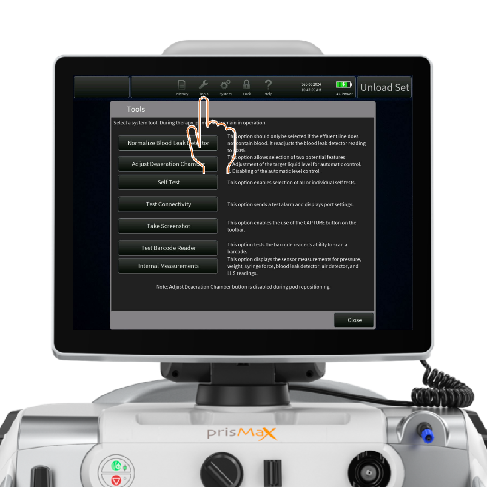
Toolbar - Tools
Tap the icon to access the TOOLS menu.
Provides access to tools for handling selected issues
- Select tool by tapping
- Instructions available for all tools
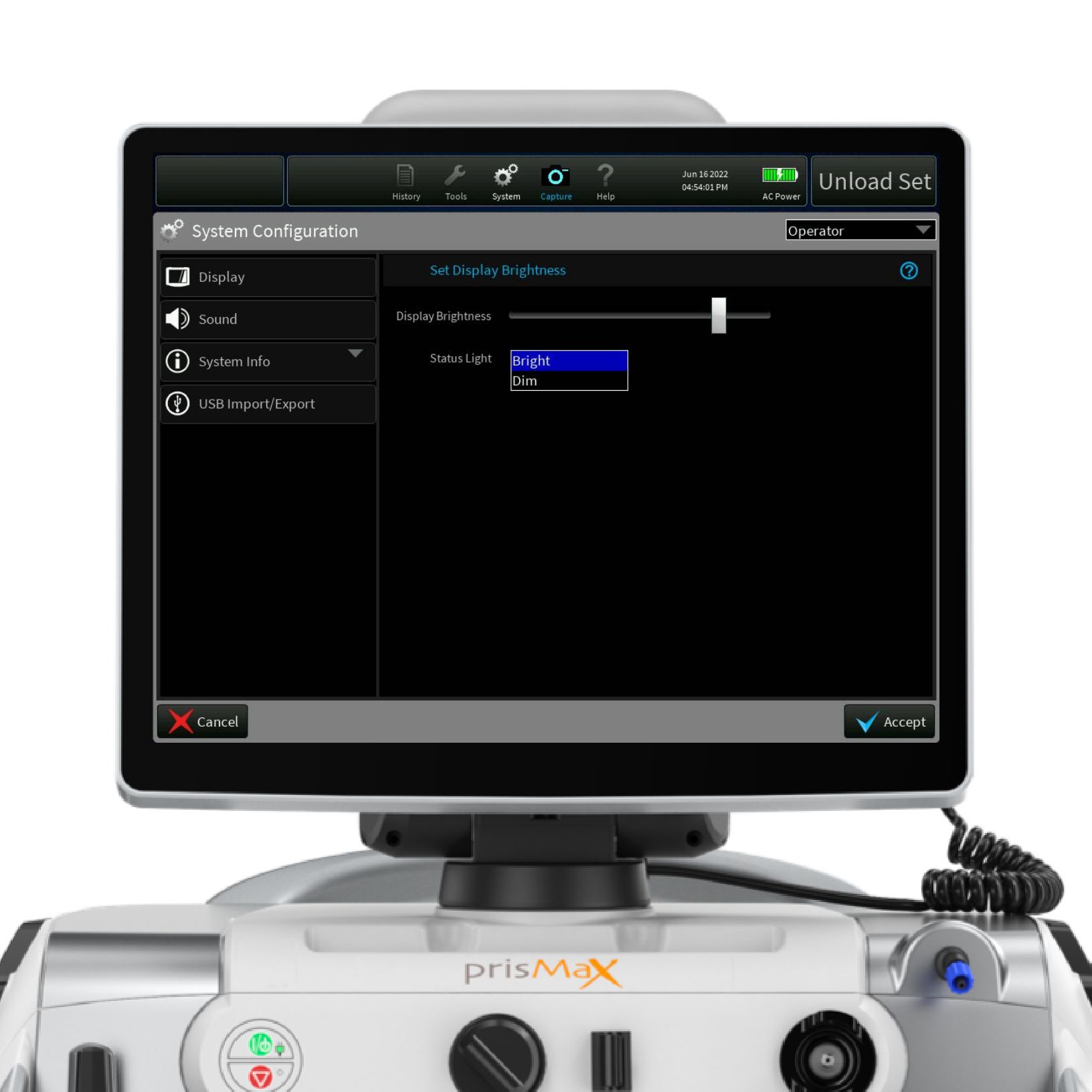
Toolbar - System configuration
- Display – set and adjust brightness and status light mode
- Sound – set and adjust volume for non-essential alarms
- System info – selected information about the device; maintenance data, software version, serial number and enabled accessories on the machine
- USB import/export – service screen for USB port options
Toolbar - Lock
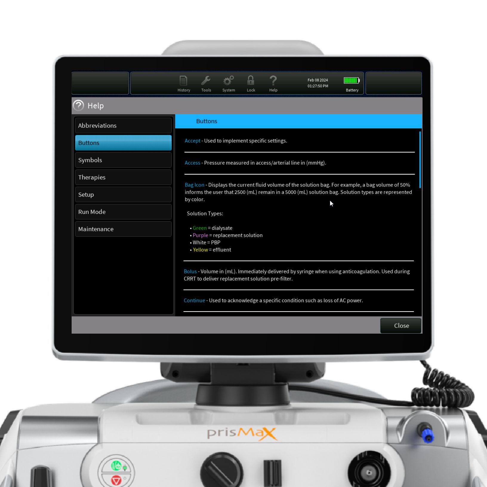
Toolbar - Help
Tap the icon to access selected topics and relevant information.
- Abbreviations
- Buttons
- Symbols
- Therapies
- Setup
- Run Mode
- Maintenance
Toolbar - Date/time/power
Shows current date and time.
Shows power source (AC or battery) and battery level.
The button changes title and function depending on the operating mode
STOP
END
CANCEL
In THERAPY mode the STOP button stops all motors and closes the RETURN CLAMP

Main screen - Bag status
Press the BLUE area on the screen to bring up schematics of the fluid bags.
If using the Auto Effluent set, it can be changed during therapy by selecting the Change AE set option.
It shows the time left on each bag change before a change is needed in hours and as minutes left when there is less than one hour remaining.
Press/Click on relevant bag icon for the CHANGE BAG instruction screen.
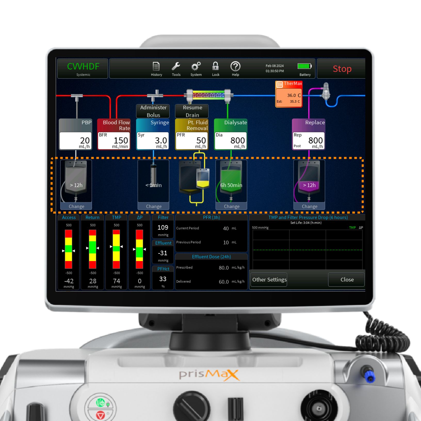
Main screen - TherMax
View current temperature set for the TherMax blood warmer.
Press/tap the TherMax box to enable and disable the blood warmer and to adjust the temperature.
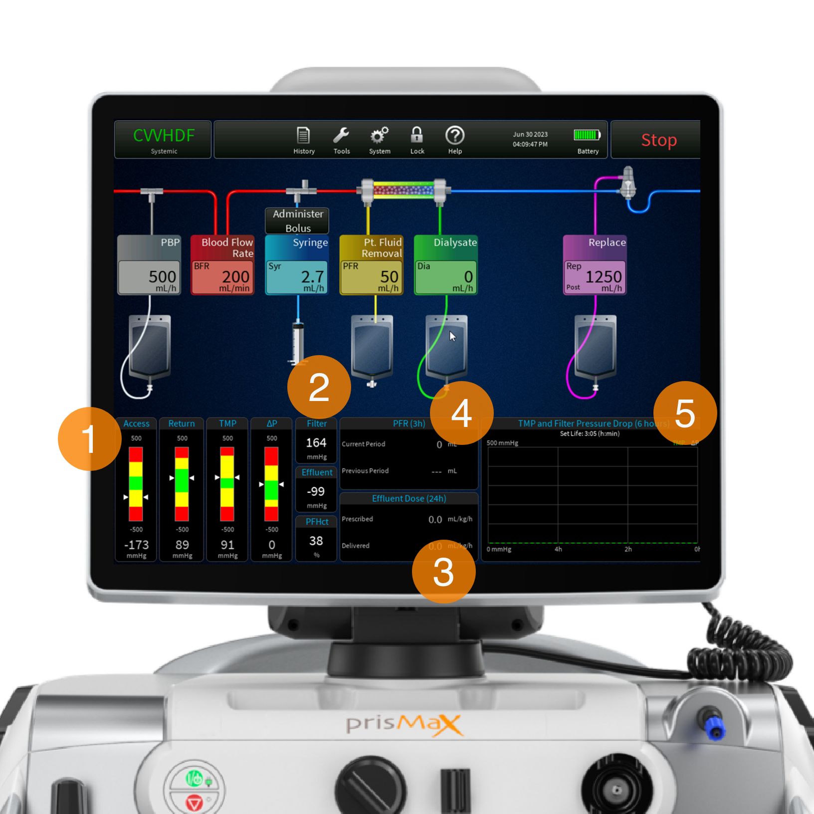
Operation parameters
The operation parameters section is built up around 5 sections:
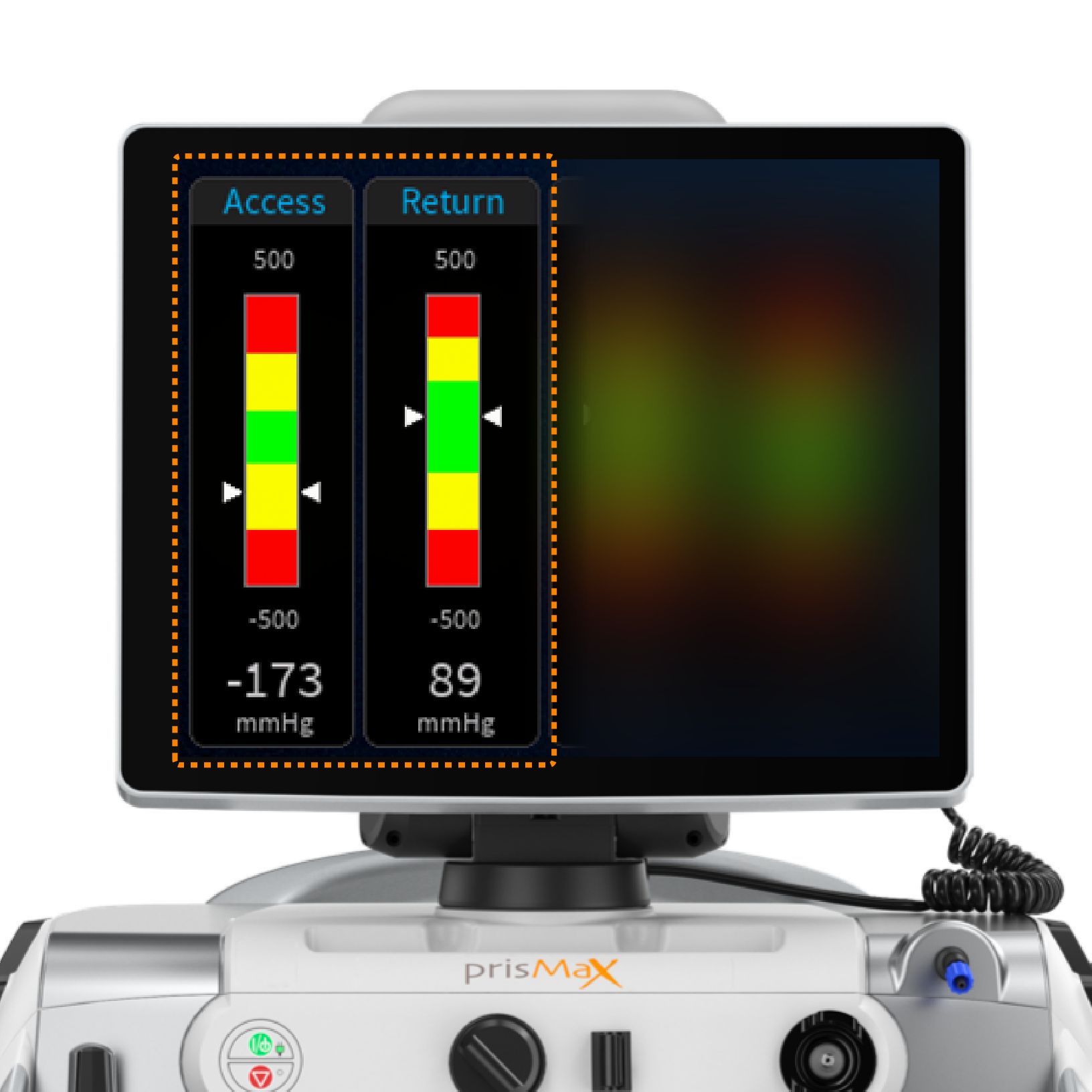
- PRESSURE BARS
Displays pressure bars, ACCESS, RETURN, ΔP (filter pressure drop) TMP (transmembrane pressure). The pressure bars indicate the current pressure measurement level (white arrows), operating range, and alarm limits, including numeric pressure levels displayed. - SINGLE DATA
Single data: FILTER (filter pressure), EFFLUENT (effluent pressure) = calculated values from Pressure Bars. PFHct (post filter hematocrit). - EFFLUENT DOSE
Shows prescription value and what has been delivered (for more detailed view = HISTORY). - PFR (PATIENT FLUID REMOVAL)
Volume of fluid removed from the patient (for more detailed view = HISTORY). - PRESSURE HISTORY GRAPH
Displays the filter drop pressure and the TMP/TMPa (as applicable) pressure over the last 6 hours of treatment and current set life (hr:min). Also shows the set life.
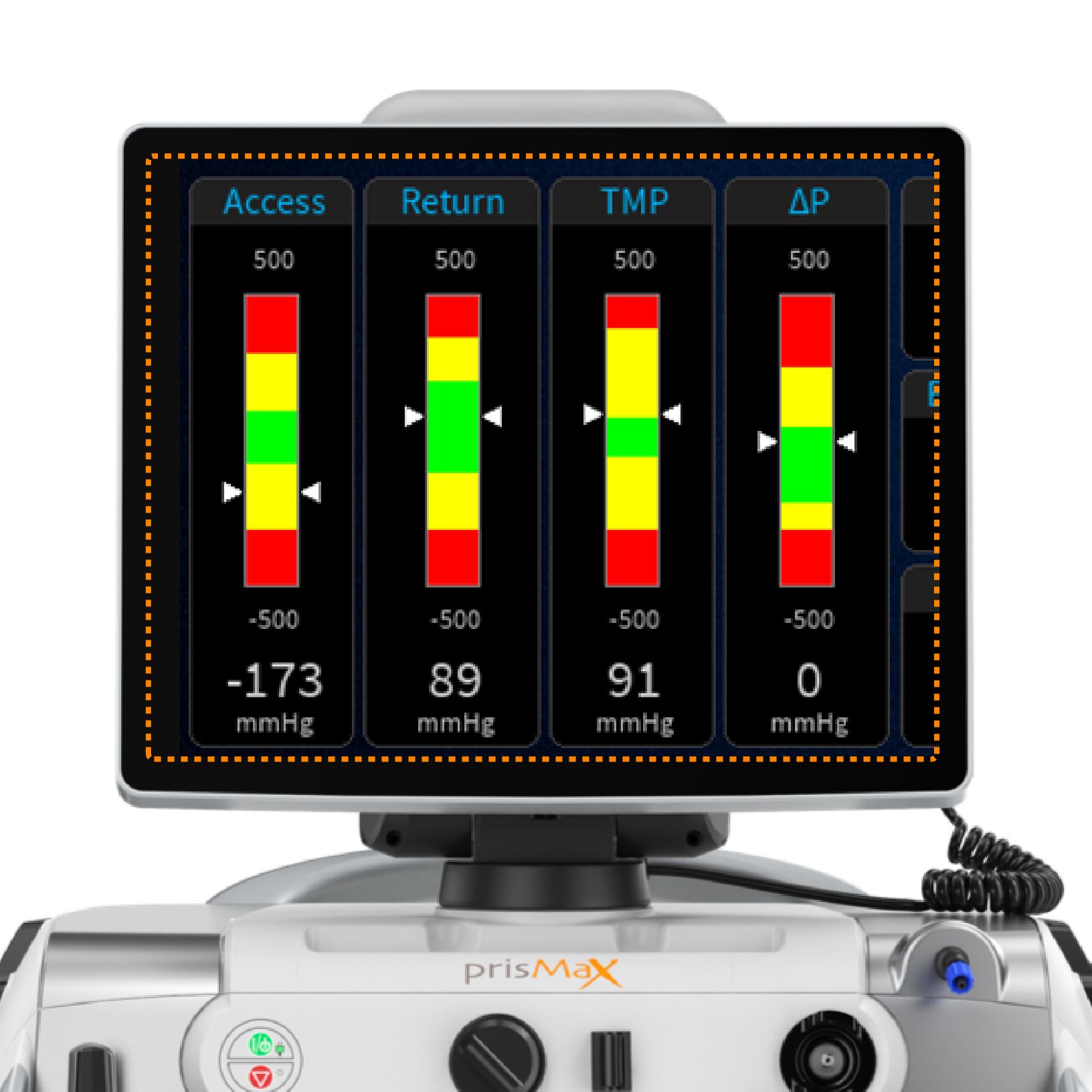
Pressure bars
Pressures are displayed in the form of pressure bars and numerics.
The pressure bars indicate the current pressure measurement, operating range, and alarm limits. The therapy in use determines which pressure bars are displayed.

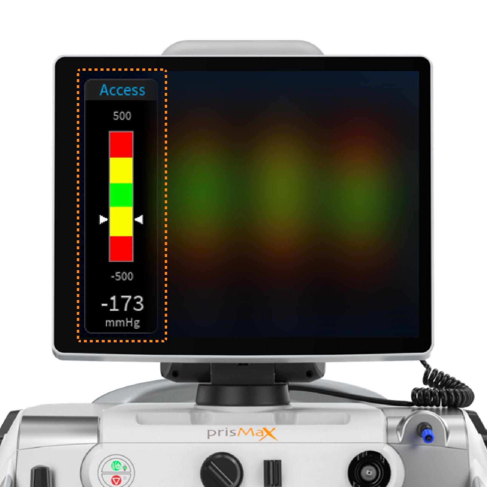
Pressure bars - schematics
Pressures are displayed in a form showing the normal operating range (green), advisory pressure levels (yellow), and warning limit levels (red).
White arrows indicate the current level.
A numeric pressure level is also displayed.
Pressure bars are grey when operating ranges are being established and during self-tests.
The operations screen displays data that is monitored during treatment.
Pressure bars - operating point
During therapy, the software stores a reference pressure value for each pressure, called the pressure operating point. The machine continually compares the current pressure at each monitoring site with the reference value to sense changing pressure conditions.
Pressure operating points are first set shortly after treatment begins.
To maintain pressure monitoring accuracy during treatment, the machine
updates pressure operating points after any of the following happens:
- Blood flow rate change
- Blood pump restart
- Alarm reset
- Self-test
Pressure bars - functionality
ACCESS and RETURN pressure (green state)
Normal access pressure can be negative or positive, depending on the access connection. Normal return pressure is nominally positive.
The normal access and return operating range is set from the operating point:
For blood flows of <200 mL/min, the operating point is ±50 mmHg; for blood flows of >200 mL/min or more, the operating point is ±70 mmHg from the calculated pressure point. If the operating value (white arrows) stays within the “green” range, the therapy will run with no alarms
ACCESS and RETURN pressure (yellow and red state)
When the operating pressures move outside the normal operating ranges (green) an alarm will be triggered to notify the operator.
An advisory or caution alarm is declared for the “yellow” advisory pressure range.
A warning alarm is declared for the “red” pressure range.
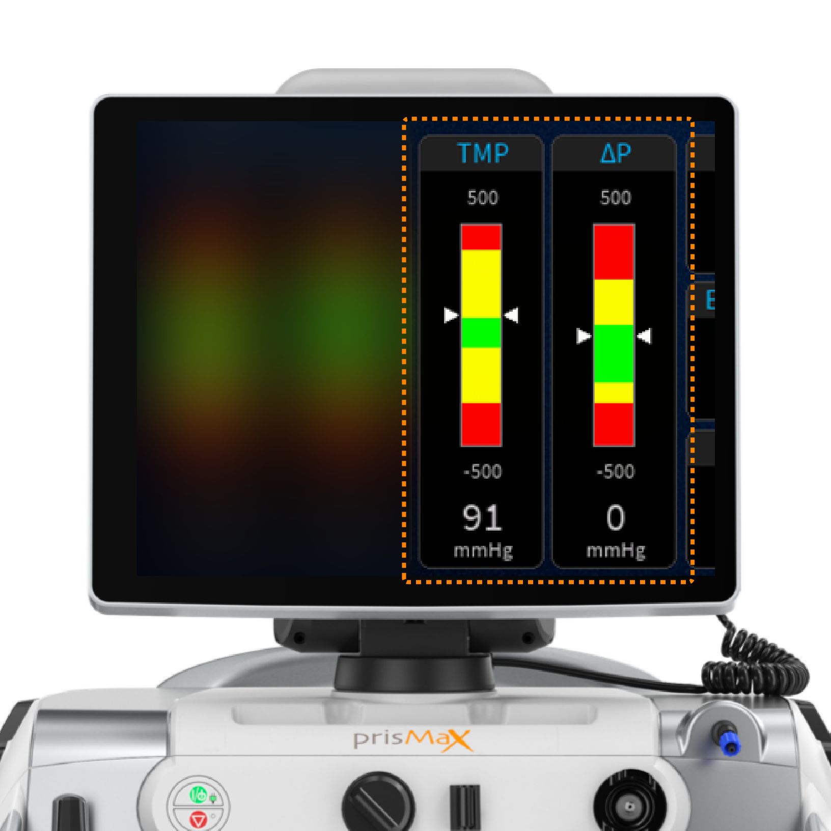
Pressure bars - functionality
CRRT: TMP (transmembrane pressure) ΔP (filter pressure drop)
TPE: TMPa (access transmembrane pressure) ΔP (filter pressure drop)
The machine uses the pressure data to calculate ΔP, TMP, or TMPa.
ΔP is calculated to determine the pressure conditions in the filter blood compartment as blood moves through the filter.
TMP (CRRT) is the applied pressure across the filter membrane during operation and shows the pressure difference between the blood and fluid compartments.
TMPa (TPE) is the pressure difference between the blood and fluid compartments at the inlet side of the filter.
The device, set, and therapy type will determine the default pressure alarm limits.
ΔP, TMP, and TMPa pressures (green state)
The filter operates within the normal parameters set for the filter in use.
ΔP, TMP, and TMPa pressures (yellow and red state)
As the pressures trend or move towards the “yellow” or “red” regions, these calculated pressures are used to notify about clotting or membrane pore plugging (clogging) in the filter and, if extensive enough, notify that a change of set is required.
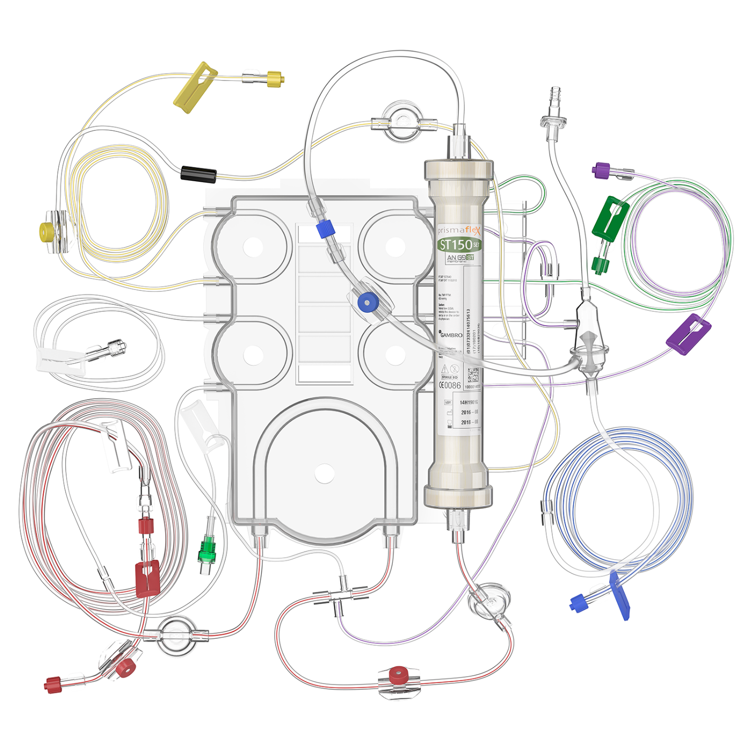
Connecting disposable sets
Get an overview of the principles behind the disposable filter set and how it is connected to the PrisMax machine.
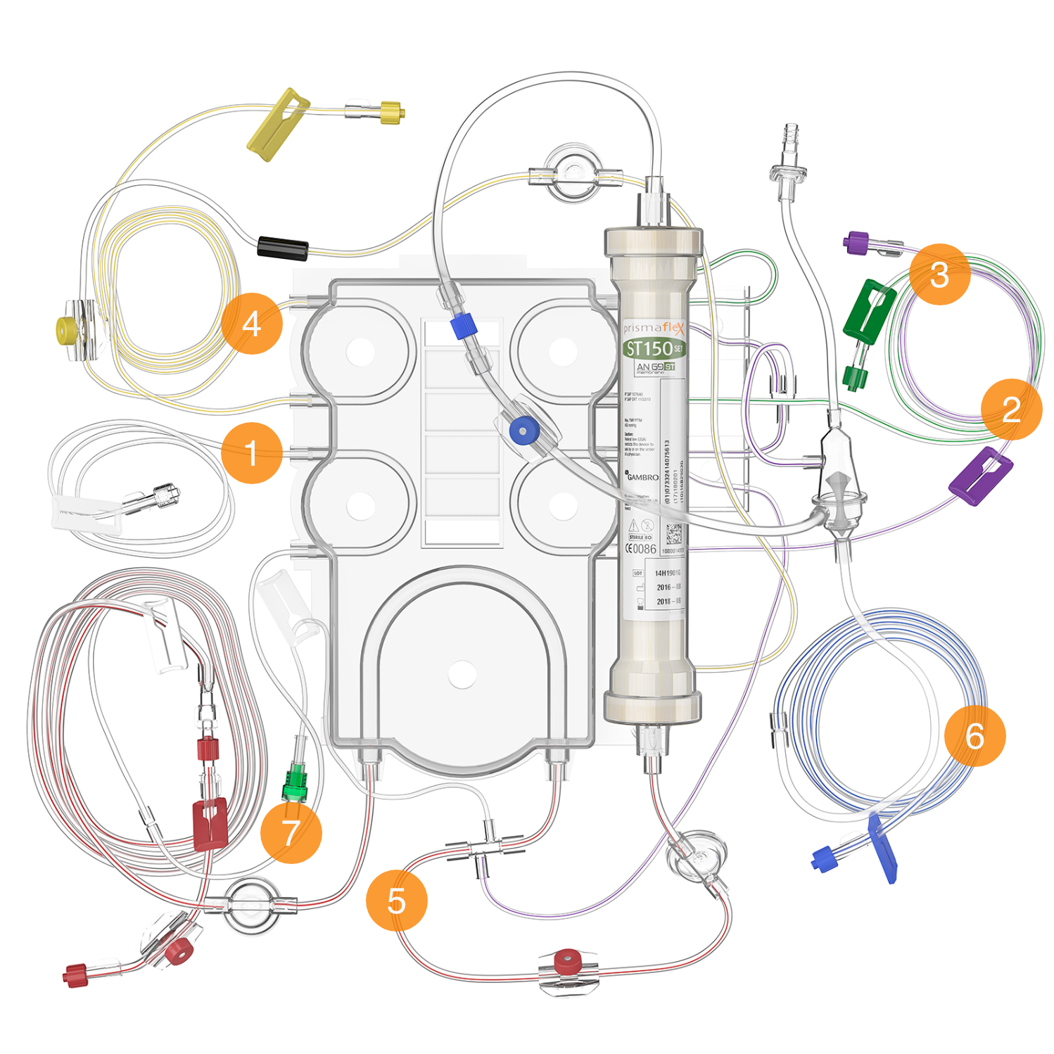
The lines
- PBP LINE (WHITE-STRIPED)
This line carries prescribed infusion solution from the bag on the PBP scale to the blood access line. If citrate anticoagulation is in use, the PBP line carries the citrate solution. - REPLACEMENT LINE (PURPLE-STRIPED)
Carries replacement solution from the bag on the replacement scale to the blood-flow path. This line is not used in all therapies. - DIALYSATE/REPLACEMENT 2 LINE (GREEN-STRIPED)
Unique to CRRT sets, this line carries solution from the green scale to the fluid compartment of the filter (for dialysate) or to the blood flow path (for replacement 2). - EFFLUENT LINE (YELLOW-STRIPED)
Transports ultrafiltrate and waste dialysate from the filter’s fluid compartment to the effluent bag. - ACCESS LINE (RED-STRIPED)
Carries blood from the blood access to the filter. - RETURN LINE (BLUE-STRIPED)
Carries blood from the filter back to the patient. - SYRINGE LINE
Used for systemic anticoagulation, this line carries anticoagulant from the syringe to the blood flow path. For regional anticoagulation, it carries calcium to the patient connection. It includes a non-return valve to prevent blood from diffusing into the syringe line.
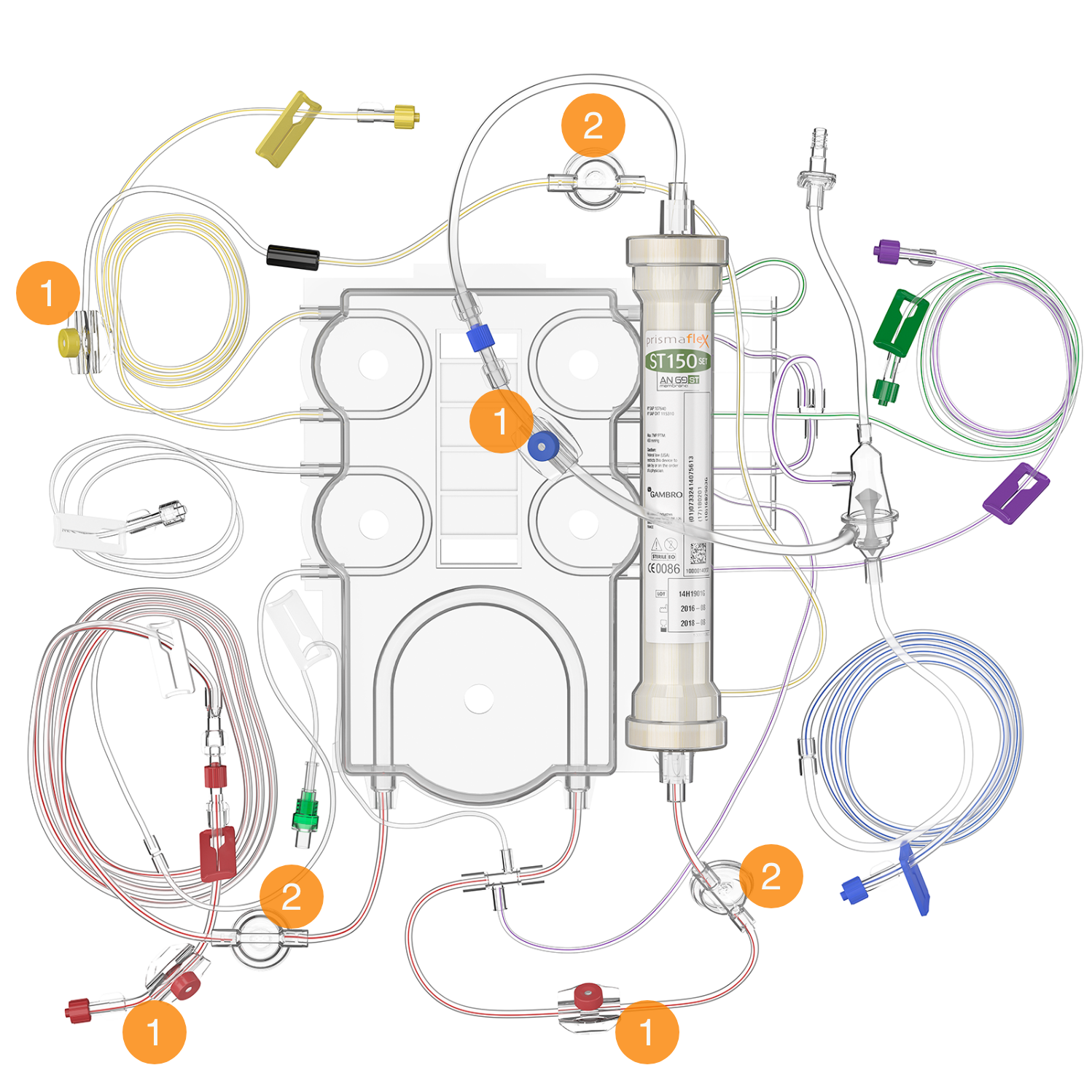
Sample sites & pressure pods
- SAMPLE SITES
Color-coded ports that allow for needle entry to obtain fluid or blood samples. These accommodate a 21-gauge or smaller diameter needle attached to a syringe. - PRESSURE PODS
Three circular pods (access, filter, and effluent) that contain a diaphragm and fit into a pressure sensor housing on the control unit, enabling non-invasive pressure monitoring.
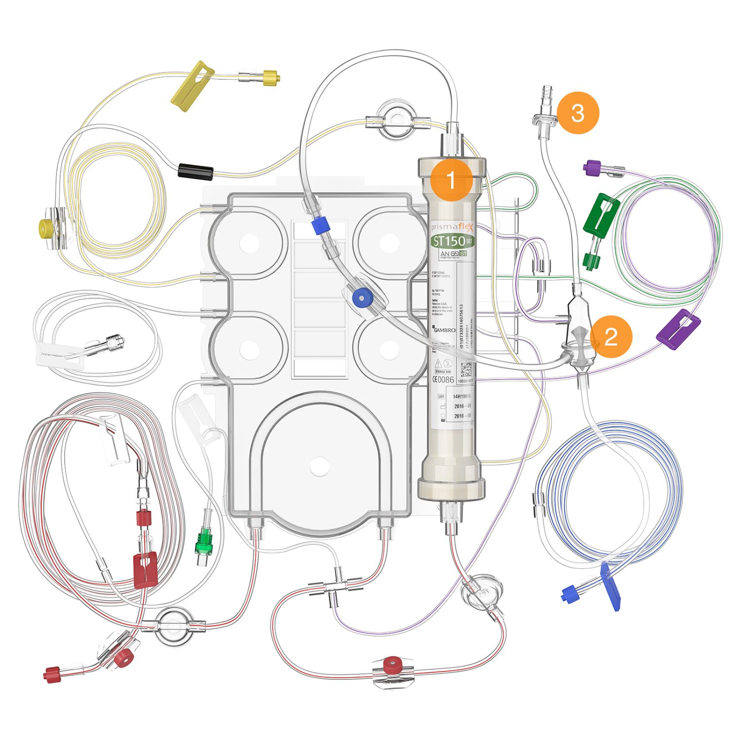
Filter & deaeration chamber
- FILTER
Characteristics of the filter vary according to the disposable set used. Specific details are provided in therapy descriptions. - DEAERATION CHAMBER
Positioned on the return line, it allows the system to manage air and add post-filter replacement solution to the return line (Blue-Striped). - CHAMBER MONITOR LINE
Connects the deaeration chamber to the return pressure port, enabling pressure monitoring and air removal. It includes a fluid barrier to protect against contamination.
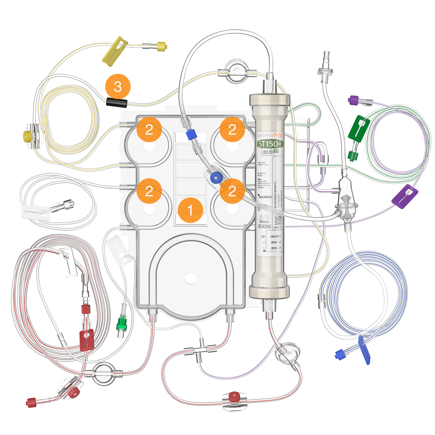
Cartridge & pump segments & discharger ring
- CARTRIDGE
The plastic component of the disposable set, containing tubing segments for the pumps and pinch valves. It covers the fluid and blood pumps when installed and facilitates automatic set loading/unloading. - PUMP SEGMENTS
Tubing lengths that fit into the raceway of each pump (blood, PBP, dialysate, replacement, and effluent). They are automatically loaded when the cartridge is installed to the loader on the front panel. - ELECTROSTATIC DISCHARGER RING
Discharges electrostatic voltage from the set, which can cause artifacts cardiac monitors.
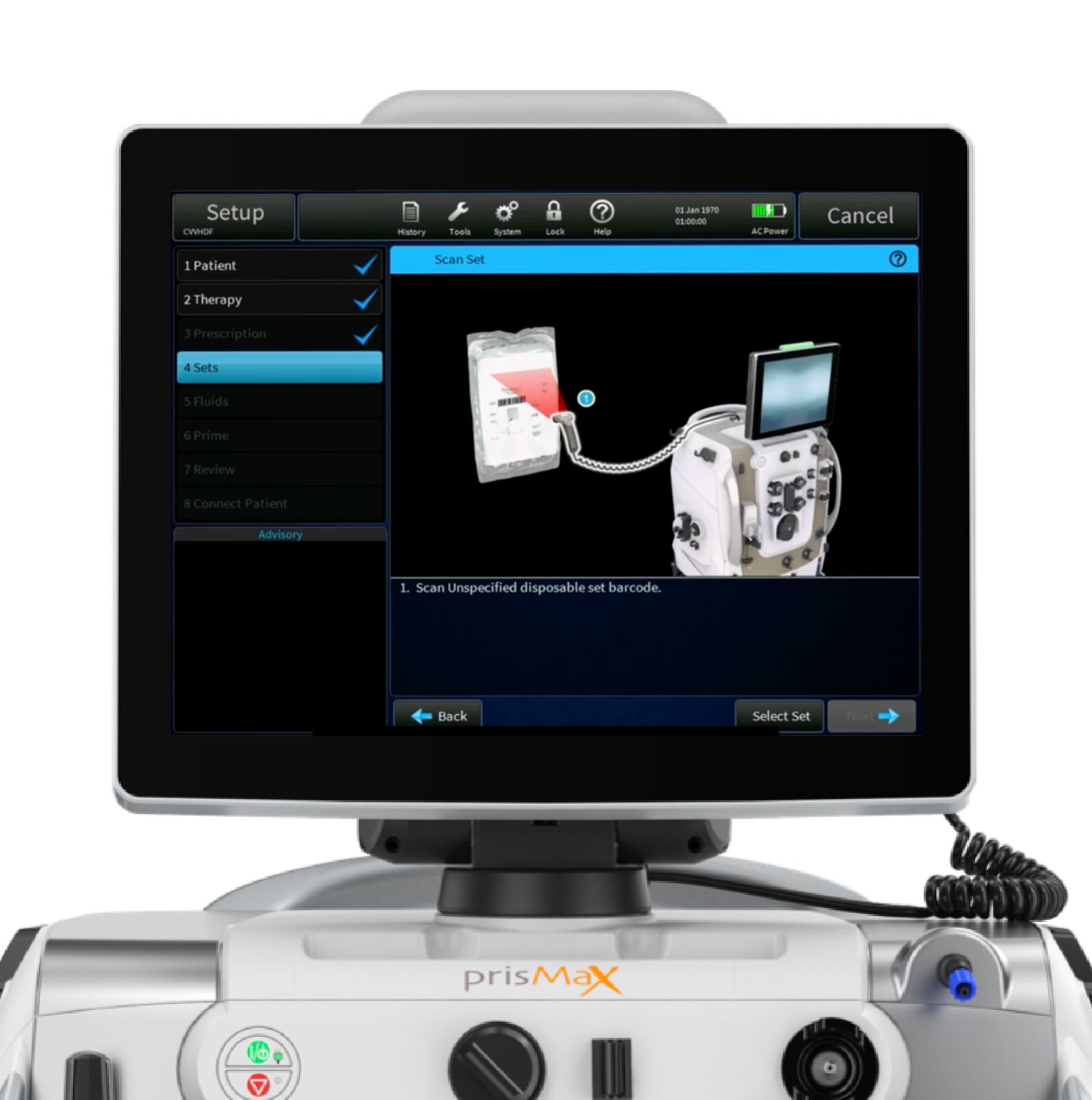
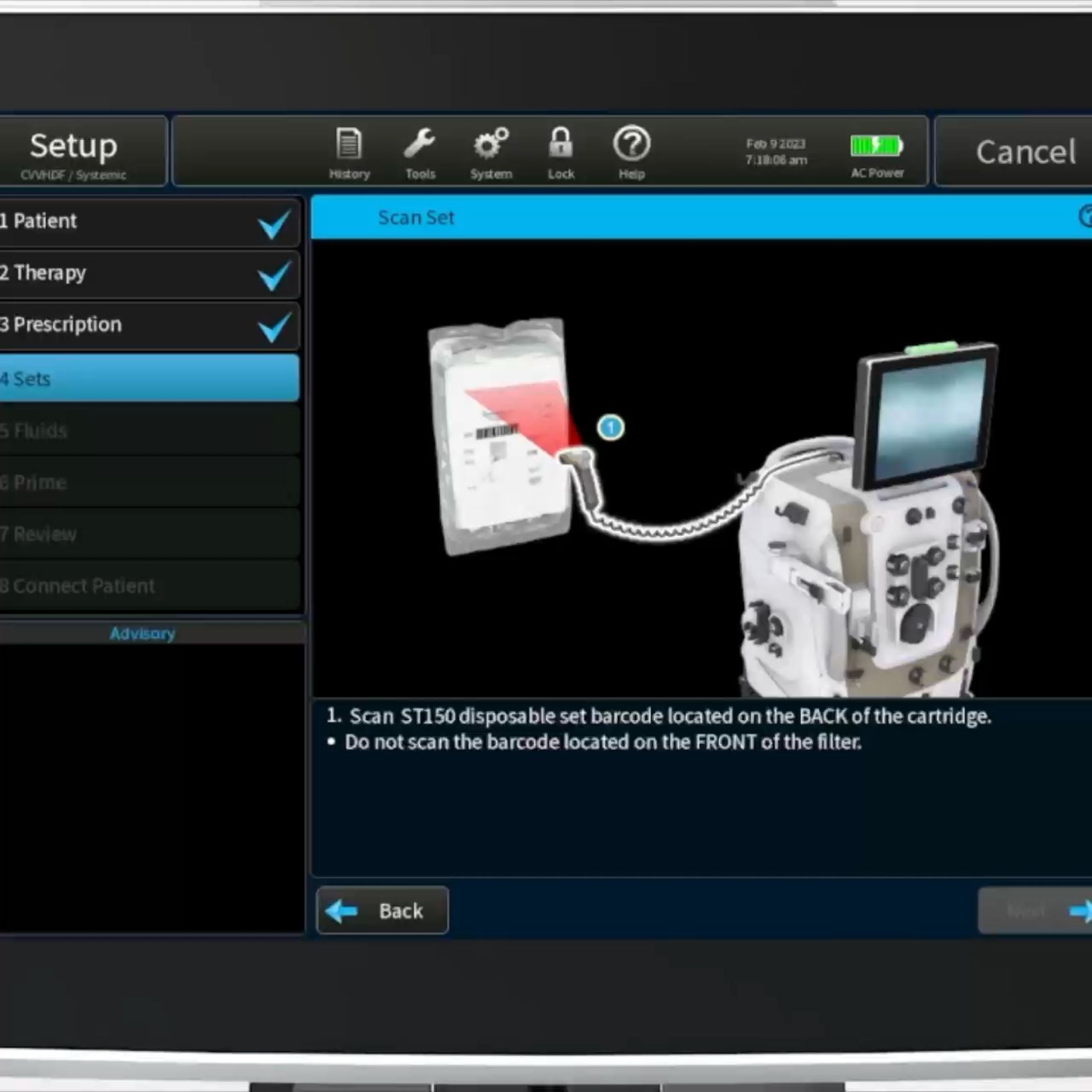
Barcode
Scan the unique barcode to secure a match between the filter set and the set type selected in the SETUP menu on the PrisMax.
Unpacked set
The filter set contains the filter membrane, filter casing and all required connections.
Disposable set lines and connections correspond to ports, clamps, pumps, and associated scales, and they are color-coded to facilitate intuitive connection.
Filter set connected
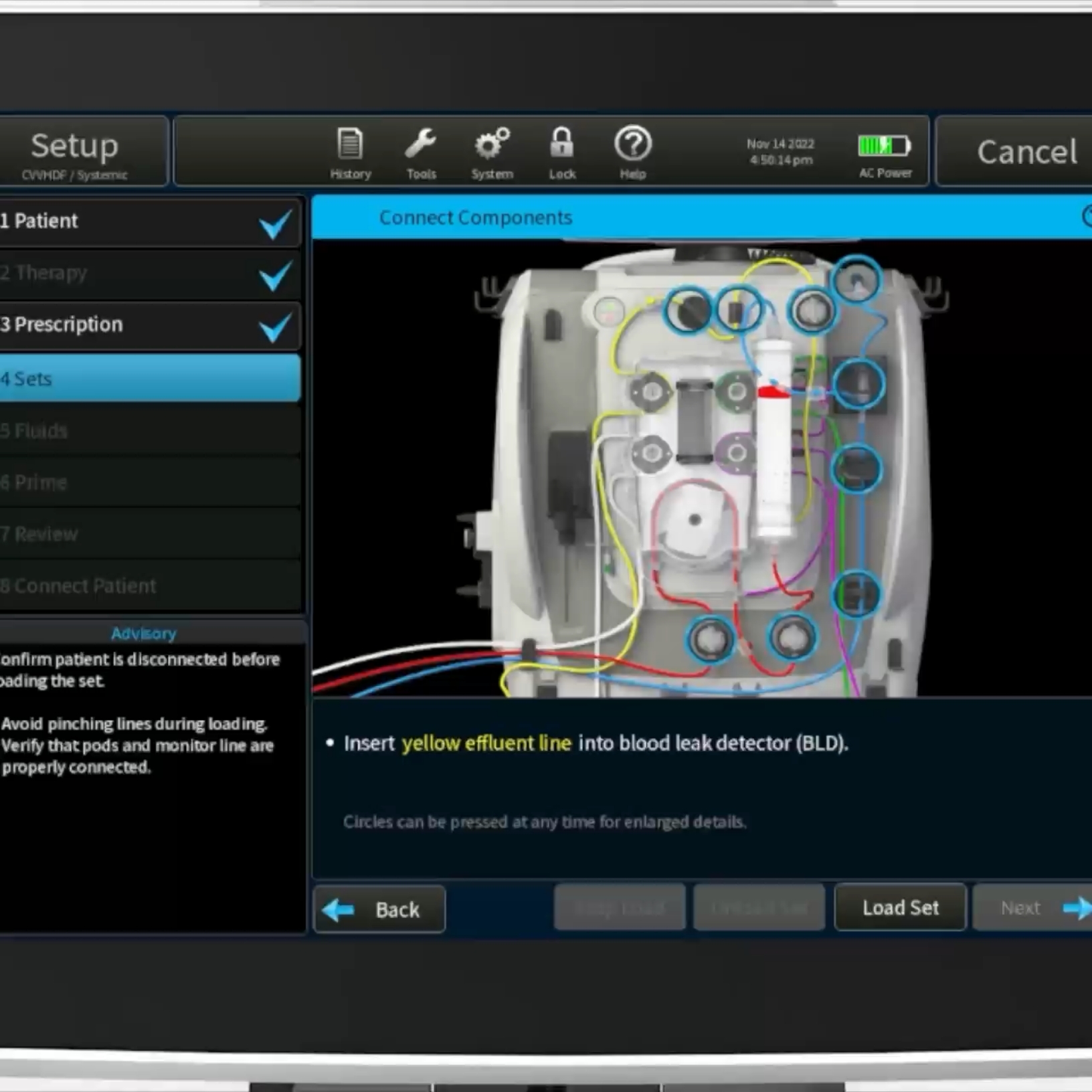
On-screen installation instructions
Once the filter set is attached, onscreen step-by-step instructions will guide the connection of the components.
Tap the corresponding blue circle to access additional information on the specific connection.
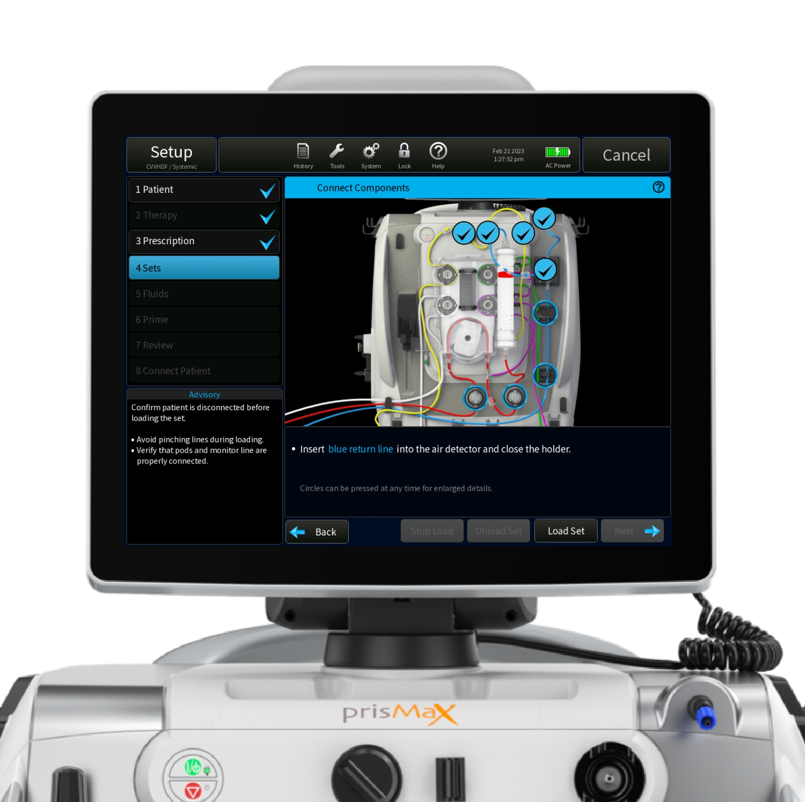
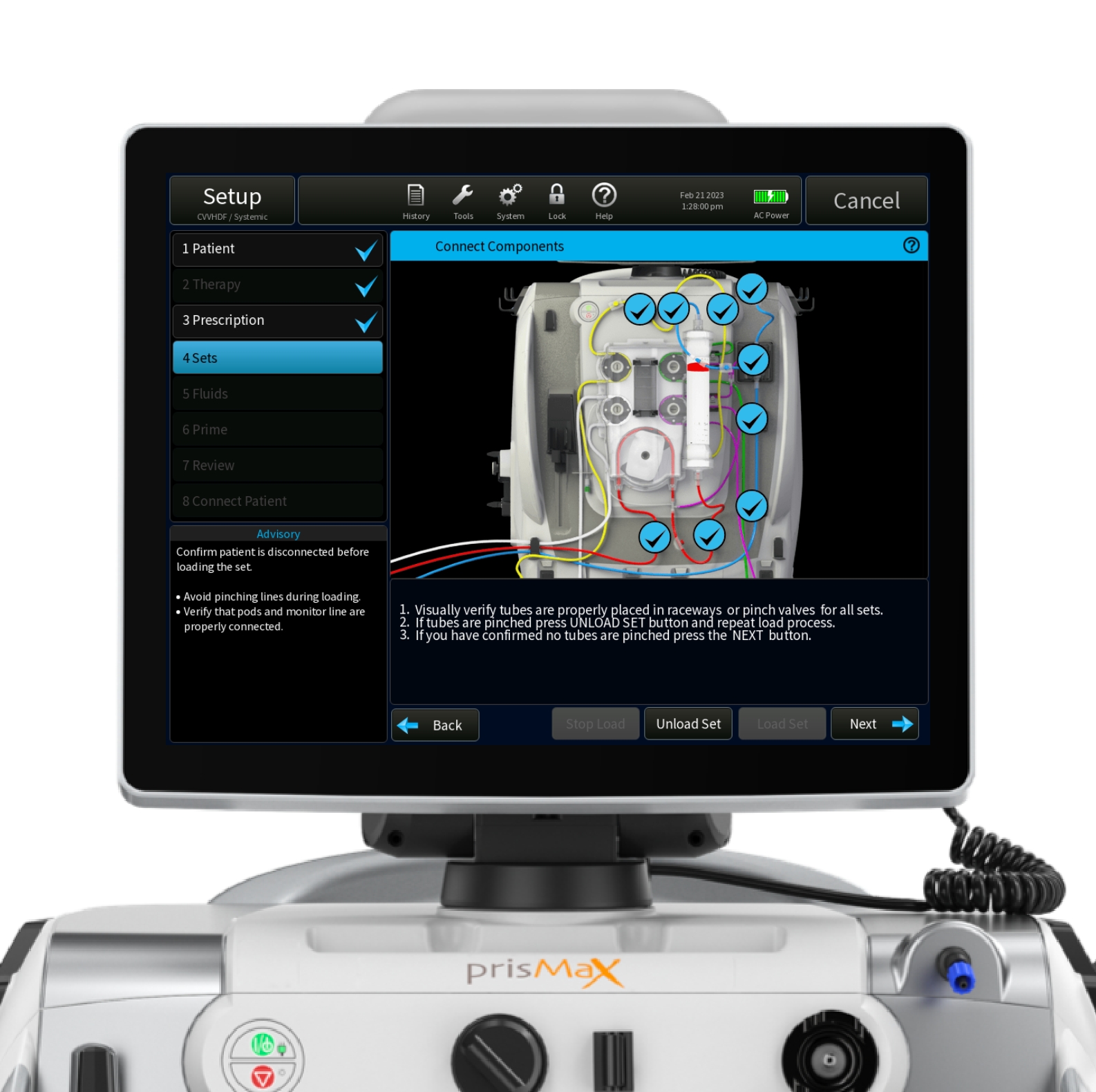
Connect components
When all components of the set are connected, tap ‘Load Set’ to load set.
How to power up the machine
- ATTACH THE AC POWER CORD TO AN AC POWER SOURCE
(Power cords are country-specific) - TO POWER ON THE CONTROL UNIT, PRESS THE GREEN ON/STANDBY BUTTON ON THE FRONT PANEL
- THE CONTROL UNIT POWERS UP AND THE START SCREEN APPEARS
How to power up the machine
ON/STANDBY BUTTON
Turns the PrisMax system on or places it in standby. When the system is on, the display and all electronics are on. Press and hold to enter standby. When the system is in standby, all electronics are off, except for power supply and battery charging.
POWER INDICATOR (GREEN)
Alternating current (AC) or battery power connected to the system. On: system running on AC. Off: no AC. Flashing: running on battery or battery charging during standby mode.
STOP BUTTON
Stops all motors and closes the return clamp. This provides an independent way to stop the device if the screen fails.
STOP INDICATOR (YELLOW)
Control unit is stopped (all pumps stopped).

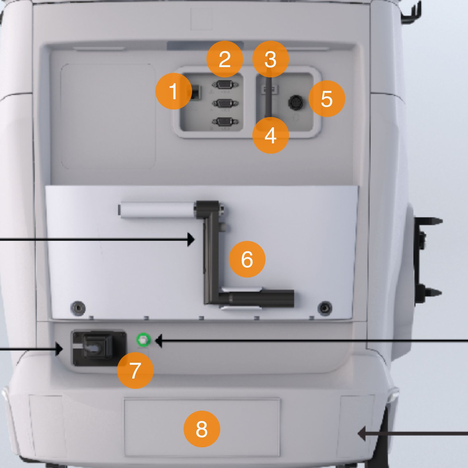
The back panel elements
- ETHERNET CONNECTOR
- SERIAL PORTS
Connections for data exchange - USB PORT
- WIFI ANTENNA CONNECTOR
Enabling WIFI connectivity (optional for TrueVue connectivity) - REMOTE ALARM CONNECTOR
To connect to the call-light system or alarm system of the hospital - HAND CRANK
Allows manual pump operation to return blood to the patient or to turn fluid pumps. For emergency situations only - POWER SOCKET
A/C power connection - SERIAL NUMBER
Unique serial number of the machine